Jump to content

Photo

Removing cluster and adding warning lights

- - - - -

  • Please log in to reply
15 replies to this topic

#1
Mark McCallister

Mark McCallister

    Member

  • Members
  • PipPipPip
  • 164 posts
  • Location:Gainesville, FL
  • Region:Central Florida
  • Car Year:1991
  • Car Number:40

'91 1.6...I would like to remove the instrument cluster which is now largely redundant to the Traqdash.


To replace the cluster's Alternator, Check Engine, and Brake warning lights, and pick up the tach, I need to pick up those signals from the harness connections that would have gone to the cluster.  I would like to avoid frying anything.  :)  Currently I am pulling the tach signal from the handy Tach terminal on the back of the cluster.


Is it as easy as the below, am I reading the polarities right, and are there other complications?


Tach:  Connect wire 1H to tach sense on the Traqdata.


Alternator Light:   Connect wire 1G to warning bulb and then other side of bulb to +12V IGN.  Q: What are those two unlabeled resisistors in parallel with the "Charge" 1.4W bulb on the diagram?


Check Engine Light:  Connect wire 1C to warning bulb and then other side of bulb to +12V IGN.


Brake Light:  Connect wire 1D to warning bulb and then other side of bulb to +12V IGN.


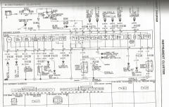
Q: On the wiring diagram, what do the numbers in circles refer to?  I can't find a key for that.


Thanks!


Scan of wiring diagram attached:

1991 Instrument Cluster Circuit Diagram


Bona fide - A bonafide Spec Miata driver

#2
Graeme

Graeme

    Junior Member

  • Members
  • Pip
  • 4 posts
  • Region:Rocky Mountain
  • Car Year:1994
  • Car Number:95
The numbers in the circle are the ground points. In the front of the wiring section there is a diagram of the ground locations.

#3
Glenn Davis

Glenn Davis

    Member

  • SMembers
  • PipPipPip
  • 245 posts
  • Location:Colorado Springs, CO
  • Region:WDCR/Mid-Atlantic
  • Car Year:2002
  • Car Number:TBD

I thought the numbers in the circles referred to where to find the connected circuitry...


Only when those numbers are sitting on a ground point do they represent ground.  For example, the 2 on Alternator (Section A) refers to the entry point in that section of the wiring diagram.


Make it Rain - Made Paypal donation of $100+ Bona fide - A bonafide Spec Miata driver

#4
Glenn Davis

Glenn Davis

    Member

  • SMembers
  • PipPipPip
  • 245 posts
  • Location:Colorado Springs, CO
  • Region:WDCR/Mid-Atlantic
  • Car Year:2002
  • Car Number:TBD

I'm guessing at the Alternator hookup a bit, but here's what it looks like:


When the potential at 1G is lower than the potential of 2K, parallel resistors allow leakage current to flow through the circuit, around the light and through the diode.  When the potential difference between 1G and the bottom of the parallel resistors becomes large enough (>0.7v), the diode will transition to forward current mode and create a path through the lamp.  This is telling you that your battery voltage exceeds your charging voltage.  The resistors look like they are there to create hysteresis.  The potential at the bottom of the resistors is lower than 2K. Once the diode snaps on, you don't want the voltage drop of the lamp to turn the diode back off.  You can choose the resistor combination to assure this doesn't happen.


Make it Rain - Made Paypal donation of $100+ Bona fide - A bonafide Spec Miata driver

#5
Randy Thieme

Randy Thieme

    Member

  • SMembers
  • PipPipPip
  • 277 posts
  • Region:Oregon
  • Car Year:1993
  • Car Number:51

...Once the diode snaps on, you don't want the voltage drop of the lamp to turn the diode back off.  You can choose the resistor combination to assure this doesn't happen.


For those of us who are marginally circuit-knowledgable can we get a quick formula or rule of thumb please?  For example, if my lamp is an LED with some internal resistance rx what resistor combination to use.  Thanks.


Make it Rain - Made Paypal donation of $100+ Bona fide - A bonafide Spec Miata driver

#6
Glenn Davis

Glenn Davis

    Member

  • SMembers
  • PipPipPip
  • 245 posts
  • Location:Colorado Springs, CO
  • Region:WDCR/Mid-Atlantic
  • Car Year:2002
  • Car Number:TBD

For those of us who are marginally circuit-knowledgable can we get a quick formula or rule of thumb please?  For example, if my lamp is an LED with some internal resistance rx what resistor combination to use.  Thanks.

An LED is a diode as opposed to the incandescent in the wiring diagram, so I'm not sure you need a resistor in parallel.  You will want to limit current with a series resistor if the LED does not have a built in resistor.  I would try a built in resistor LED that is rated for 12v since that is about what it will see when the alternator craps out.


I don't have access to the wiring diagram for the alternator section, so I'm assuming that point "2" merely goes to a reference voltage in that circuit.  If not, it may not operate as I understand.


Make it Rain - Made Paypal donation of $100+ Bona fide - A bonafide Spec Miata driver

#7
Adax

Adax

    Member

  • Members
  • PipPipPip
  • 208 posts
  • Location:Atlanta
  • Region:ATL
  • Car Number:49

Mark,


I just removed the diode from the circuit board (make sure you orient it the corrrect way) but since you are using LED's, I'm not sure it's needed. I did not use a resistor and did use the diode with my LED alt light and it is working fine.


Here's the diode


IMG_1270.JPG


IMG_1271.JPG


IMG_1272.JPG


IMG_1273.JPG


Alan Cross

My build blog

2017 SARRC SM Champion

2016 SARRC SM ECR Champion

Donor - Made PayPal donation Bona fide - A bonafide Spec Miata driver ARRC Champion - Won the ARRC Race in a Spec Miata We have a Winnah! - Won their 1st race... Congratulations! Bona fide - A bonafide Spec Miata driver

#8
Glenn Davis

Glenn Davis

    Member

  • SMembers
  • PipPipPip
  • 245 posts
  • Location:Colorado Springs, CO
  • Region:WDCR/Mid-Atlantic
  • Car Year:2002
  • Car Number:TBD

Wow.  It's funny to see the lengths to which one will go to maintain a single-layer circuit board.  Nice use of jumpers...


Alan, since yours goes to the PCM, you might have a sense circuit that would eliminate the need for the parallel resistors that are required in an analog approach.


Mark, can you add a photo of the Alternator (Section A) wiring diagram that shows where the charge light is connected in?


Make it Rain - Made Paypal donation of $100+ Bona fide - A bonafide Spec Miata driver

#9
Mark McCallister

Mark McCallister

    Member

  • Members
  • PipPipPip
  • 164 posts
  • Location:Gainesville, FL
  • Region:Central Florida
  • Car Year:1991
  • Car Number:40

Excellent, thanks!  Like any good analog technology, this circuit seems to be simultaneously simple and clever.  :)


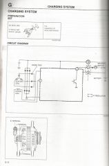
Below is my scan of that page in the FSM - it doesn't show anything more than the one above.


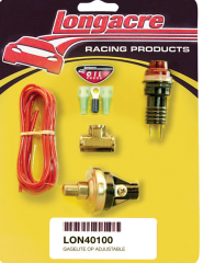
I'm actually using the Longacre replacement lamps, like the one that come in their warning light kits.  These are standard #194 incandescent bulbs that show 4.9 ohms to my multimeter.


Screen Shot 2013 12 13 At 9.27.38 PM


The bulb and diode are just left of where it says "ignition switch."

Alt circuit

Bona fide - A bonafide Spec Miata driver

#10
Glenn Davis

Glenn Davis

    Member

  • SMembers
  • PipPipPip
  • 245 posts
  • Location:Colorado Springs, CO
  • Region:WDCR/Mid-Atlantic
  • Car Year:2002
  • Car Number:TBD

It looks like the light is referenced against the regulated voltage, as expected.  I have no idea what all those other parts are with the bulb and socket, unless it is some kind of potentiometer/rheostat to control bulb brightness.


I'm getting ready to do a similar panel replacement and here's what I plan:


Find an available point for switched 12v and create another fused circuit for all of my panel lighting.  Directly wire into the warning/indication circuits that I want to keep using 12v LED's with onboard resistors between my new 12v circuit and the instrument panel harness.  A decent electronics supply will have many colors/sizes/powers of LED's.


I'm not a big fan of Radio Shack, but http://www.radioshac...kw=12v led&sr=1


Make it Rain - Made Paypal donation of $100+ Bona fide - A bonafide Spec Miata driver

#11
Mark McCallister

Mark McCallister

    Member

  • Members
  • PipPipPip
  • 164 posts
  • Location:Gainesville, FL
  • Region:Central Florida
  • Car Year:1991
  • Car Number:40
Yeah, that pic is of some random warning light sender kit, I just wanted you to see what the longacre bulb looked like.
Bona fide - A bonafide Spec Miata driver

#12
Mark McCallister

Mark McCallister

    Member

  • Members
  • PipPipPip
  • 164 posts
  • Location:Gainesville, FL
  • Region:Central Florida
  • Car Year:1991
  • Car Number:40
I've installed an auxiliary fuse box for all the new auxiliary electronics, and a ground bus bar as part the project, to make all the auxiliary electronics wiring a little more organized. The prevalence of in-line fuses in random places and redundant wire runs was getting annoying. :)
Bona fide - A bonafide Spec Miata driver

#13
Glenn Davis

Glenn Davis

    Member

  • SMembers
  • PipPipPip
  • 245 posts
  • Location:Colorado Springs, CO
  • Region:WDCR/Mid-Atlantic
  • Car Year:2002
  • Car Number:TBD

I should have added that the resistance on a voltmeter is useless for an incandescent lamp as the filament resistance increases a great deal as it heats to a high enough temperature to emit light.  The lit resistance can be calculated by knowing the power of the lamp at the voltage of the circuit.  In the original circuit, the lit resistance of the lamp was about 100 ohms.  This is calculated by the equation R = V^2/P, or 144/1.4  The voltmeter resistance is probably along the lines of what you saw on the Longacre lamp.


Again, with the availability of LED's, there's really not a good reason to stay with incandescent lamps.


Make it Rain - Made Paypal donation of $100+ Bona fide - A bonafide Spec Miata driver

#14
Mark McCallister

Mark McCallister

    Member

  • Members
  • PipPipPip
  • 164 posts
  • Location:Gainesville, FL
  • Region:Central Florida
  • Car Year:1991
  • Car Number:40
Once you take the printed circuit off the back of the cluster, the components and circuit are evident.

But now I wonder, maybe a volts gauge with a warning light threshold somewhere between battery voltage and alternator voltage would be a viable alternative to the OEM alternator light (relocated or not)?

Basically there are two things we want to know:
1) is the water pump turning, as evidenced by whether the alternator is turning.
2) is the alternator charging.
Bona fide - A bonafide Spec Miata driver

#15
Glenn Davis

Glenn Davis

    Member

  • SMembers
  • PipPipPip
  • 245 posts
  • Location:Colorado Springs, CO
  • Region:WDCR/Mid-Atlantic
  • Car Year:2002
  • Car Number:TBD
Easy to install a voltmeter and determine if the alternator is charging. I don't know about detecting a lost belt other than water temp.
Make it Rain - Made Paypal donation of $100+ Bona fide - A bonafide Spec Miata driver

#16
Jeff Wasilko

Jeff Wasilko

    Member

  • Members
  • PipPipPip
  • 272 posts
  • Location:Boston, MA
  • Region:NER
  • Car Year:1995
  • Car Number:08

Once you take the printed circuit off the back of the cluster, the components and circuit are evident.

But now I wonder, maybe a volts gauge with a warning light threshold somewhere between battery voltage and alternator voltage would be a viable alternative to the OEM alternator light (relocated or not)?

Basically there are two things we want to know:
1) is the water pump turning, as evidenced by whether the alternator is turning.
2) is the alternator charging.


I use that as a warning on my dash. I forget the set point, though.


I lost the alternator tensioner bolt once and the water temps spiked pretty quickly.


0 user(s) are reading this topic

0 members, 0 guests, 0 anonymous users