


 Sign In
 Create Account
When we looked at the short studs that came out of these hubs you can see that they are just a little bit smaller on the knurl. I guess that the ARP studs stressed the hub when they where pressed in the hub causing the failure after torquing the wheels a number of times.


Front Hub Failure

Started by
Todd Green
, 03-25-2014 09:19 PM
#21

 Posted 04-30-2014 08:13 AM
RP Performance
-

- Members
-

- 4 posts
Junior Member
- Location:Summit Point
- Region:WDC
 Back to top
 Report
#22
Posted 04-30-2014 08:55 AM
ChrisA
-

- Members
-
- 660 posts
Veteran Member
- Location:Richmond, VA
- Region:NCR
- Car Year:1999
- Car Number:58
The breaks don't appear to be related to the studs per-se, as the break lines don't run to them. They are completely intact. It is likely tire and wheel offset related fatigue and/or possible additional stress induced from pressing in the studs w/out proper flange support.
Chris
Happiness is a dry martini and a good woman ... or a bad woman.
- George Burns
#23
Posted 04-30-2014 09:25 AM
Glenn Davis
-
- SMembers
-
- 245 posts
Member
- Location:Colorado Springs, CO
- Region:WDCR/Mid-Atlantic
- Car Year:2002
- Car Number:TBD
The breaks don't appear to be related to the studs per-se, as the break lines don't run to them. They are completely intact. It is likely tire and wheel offset related fatigue and/or possible additional stress induced from pressing in the studs w/out proper flange support.
Without a stress analysis, you can't be sure. However, the stress regions created by the studs may be circumferential vs. radial, especially if there is no particular stress riser right at the stud hole. Think about it as an expanding hole. Only the very edge of the hole would be in tension, everything else would be in circumferential compression.


#24
Posted 04-30-2014 09:37 AM
FTodaro
-

- SMembers
-
- 3,084 posts
Veteran Member
- Location:Columbus Ohio
- Region:Great Lakes
- Car Year:2001
- Car Number:35
It would be nice to get a collection of the failed hubs, so PM saul and get his address ship him the failed parts with as much of an explanation of the history of the part, age, source, time in service, crashes, big offs, if you repacked it or not, for example. .
While we are speculating on the cause. i want to consider cheap steel being used in the hubs. The carbon content and how its is processed plays a big part in its performance. We know there is a difference in the steel used in rotors that same is true for the hubs.
Can you say China?
Frank
TnT Racing
SCCA Ohio Valley Region


#25
Posted 04-30-2014 10:09 AM
Glenn Davis
-
- SMembers
-
- 245 posts
Member
- Location:Colorado Springs, CO
- Region:WDCR/Mid-Atlantic
- Car Year:2002
- Car Number:TBD
I went back and looked at some "thick walled pipe" models, which are similar to what you would see with the interference fit. Looks like the model shows that tangential stresses are always greater than radial.
While it might be a good idea to look at the metallurgy, a good first step might be to put a micrometer on any wheel studs you have, as well as any stud holes in unpopulated hubs. Very small deviations in the total interference created can result in very large stress differences. In the example I looked at, a change of about 1 mil of interference of a steel/steel shaft/hub press fit resulted in almost 30,000 psi difference in tangential stress.
While this example is steel/steel and uses a 1" diameter shaft, you can see how small changes in these parts might create large differences in the stresses they see.
#26
Posted 04-30-2014 11:32 AM
SaulSpeedwell
-

- Members
-
- 792 posts
Veteran Member
- Location:NEOhio
I went back and looked at some "thick walled pipe" models, which are similar to what you would see with the interference fit. Looks like the model shows that tangential stresses are always greater than radial.
While it might be a good idea to look at the metallurgy, a good first step might be to put a micrometer on any wheel studs you have, as well as any stud holes in unpopulated hubs. Very small deviations in the total interference created can result in very large stress differences. In the example I looked at, a change of about 1 mil of interference of a steel/steel shaft/hub press fit resulted in almost 30,000 psi difference in tangential stress.
While this example is steel/steel and uses a 1" diameter shaft, you can see how small changes in these parts might create large differences in the stresses they see.
Myself and my beer-compensated metallurgist like this analysis.
I also like wheels with correct offset and avoiding long studs and spacers.
Would anyone be having LESS fun if you were running 38mm offset (like we were in 2002) and narrower, lighter, less sticky, tires?
For faster reply than PM: miataboxes>>>AT<<<gmail>>DOT<<<com
#27
Posted 04-30-2014 11:55 AM
Johnny D
-

- Moderators
-

- 6,121 posts
Veteran Member
- Location:Fremont, CA
- Region:San Francisco
- Car Year:1999
- Car Number:88
Would anyone be having LESS fun if you were running 38mm offset (like we were in 2002) and narrower, lighter, less sticky, tires?
Don't forget less expensive.
J~
2011 NASA Western Endurance Racing Championship E3 Champ


#28
Posted 04-30-2014 01:59 PM
ppridday
-

- Members
-
- 32 posts
Member
- Location:Minnesota
- Region:Land O' Lakes
I'm not sure if anyone is interested or not, but I will be at NOLA for the PCA HPDE on May 24th and 25th. If anyone wants their hubs magnetic particle inspected (Magnafluxed) I will bring some gear along and do them. If nothing else it will give you peace of mind that it "should" be OK for the next short while. On a couple of the pictures it looked like there was some time before the ultimate failure so these could possible have been caught. Not that it means your hub is still good, but it may stop an on track failure.
Paul
There's someone in my head, but it's not me....
#29
Posted 04-30-2014 02:06 PM
Bench Racer
-
- Members
-
- 5,508 posts
Different strokes for different folks : )
- Location:Wauwatosa, WI
- Region:Milwaukee
- Car Year:1990
- Car Number:14
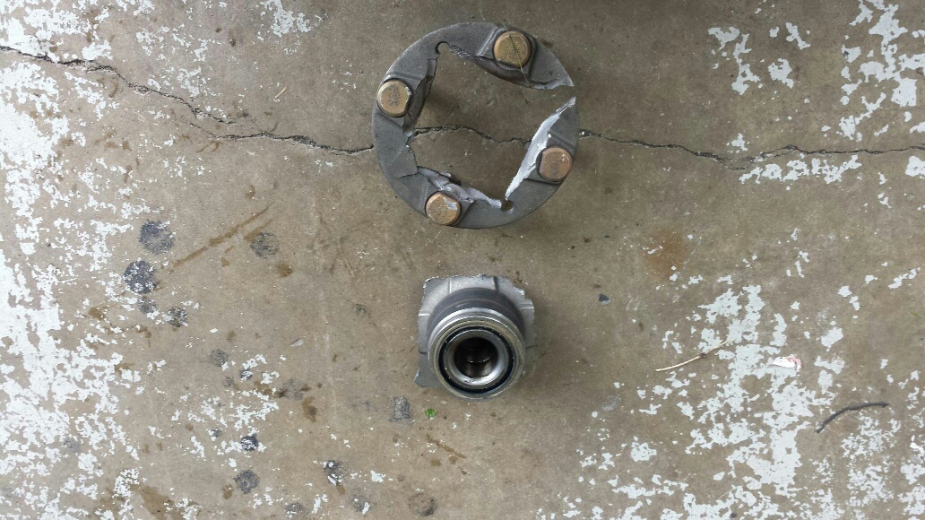
Looking at the picture long distance, the cross section of material looks a bit suspect at 4 o-clock and 6 o-clock. If in fact there are no direct cracks to the splined holes, might one of the failure root causes be the two taped holes. The material thickness is thinner suronding the taped holes than the material surrounding the splined holes. The fracture stoped at the threaded holes and busted out at 2 o-clock and looks like the failure almost busted out at 7 o-clock.
EDIT:
Just talked to the driver of a F production car that we serviced together. We installed ARP studs front and rear and the rear studs have no failed hub/flanges to date. The rear hubs have been serviced with no stud replacement. The front hubs have failed because of the outter race, but no hub/flange failure. Stud install may make a difference. When we installed the ARP studs we used spacers and an electric impact tool.

#30
Posted 04-30-2014 02:25 PM
Johnny D
-
- Moderators
-
- 6,121 posts
Veteran Member
- Location:Fremont, CA
- Region:San Francisco
- Car Year:1999
- Car Number:88
Just thinking, when it fails, you would have 1 or 2 sides/cracks fail.
Would that be the clean break it 1 and 10, and the 4 and 6 the ripping apart.?
And over torque the studs?
Torque one stud at a time, with potentional uneven torque and/or create the stress crack with one torqued and the others not?
As opposed to snug up the nuts best you can and then torque?
J~
2011 NASA Western Endurance Racing Championship E3 Champ
#31
Posted 04-30-2014 08:15 PM
FTodaro
-
- SMembers
-
- 3,084 posts
Veteran Member
- Location:Columbus Ohio
- Region:Great Lakes
- Car Year:2001
- Car Number:35
I am not a metallurgist but if the studs were the source of the stress would the cracks go to the studs and crack from that point?
Frank
TnT Racing
SCCA Ohio Valley Region
#32
Posted 04-30-2014 08:30 PM
Johnny D
-
- Moderators
-
- 6,121 posts
Veteran Member
- Location:Fremont, CA
- Region:San Francisco
- Car Year:1999
- Car Number:88
I'm not either, just looking at the stud area, it's thicker so I think the stress could come from there but not crack there.
And the thinner area was cracked perpendicular to it.
So I thought I'd through that out.
J~
2011 NASA Western Endurance Racing Championship E3 Champ
#33
Posted 05-01-2014 06:45 AM
Bench Racer
-
- Members
-
- 5,508 posts
Different strokes for different folks : )
- Location:Wauwatosa, WI
- Region:Milwaukee
- Car Year:1990
- Car Number:14
Post #1 picture shows a similar broken pattern of flat sides of a square to each of the 4 studs/holes the same as post picture #20. Any more broken hubs out there show a similar broken pattern?
#34
Posted 05-01-2014 10:51 AM
FTodaro
-
- SMembers
-
- 3,084 posts
Veteran Member
- Location:Columbus Ohio
- Region:Great Lakes
- Car Year:2001
- Car Number:35
another issue to look at. some of the rotors do not have a recess area that the fatter part of the stud fits into at the base, If you know what i am trying to say. so if the rotor was not flush with the hub the stress on the hub would not be uniform.
So lets save hubs and rotors to examine.
Frank
TnT Racing
SCCA Ohio Valley Region
#35
Posted 05-01-2014 11:07 AM
Keith Novak
-

- SMembers
-
- 1,128 posts
Steadily Improving Member
- Location:Seattle
- Region:Northwest/Oregon
- Car Year:1995
- Car Number:88
another issue to look at. some of the rotors do not have a recess area that the fatter part of the stud fits into at the base, If you know what i am trying to say. so if the rotor was not flush with the hub the stress on the hub would not be uniform.
So lets save hubs and rotors to examine.
If people aren't countersinking the back of their rotors to accommodate for the thick bit of the stud sticking out to make the rotor sit flat they definitely should.
- FTodaro likes this
#36
Posted 05-01-2014 11:17 AM
Keith Novak
-
- SMembers
-
- 1,128 posts
Steadily Improving Member
- Location:Seattle
- Region:Northwest/Oregon
- Car Year:1995
- Car Number:88
As I look at the square shape of that fracture, it looks like it is caused by bending stresses during corners applied to a 4-lug hub. The square fracture shape lines up neatly with the bolt pattern. When one stud is top and one bottom, the two at the middle are along the neutral axis. The top of the wheel is getting bent one direction and the bottom the other. As the wheel rotates, each stud area cycles between tension on one side and compression on the other.
That is your classic fatigue scenario. This is why 4 lug wheels are not very structurally sound. The stresses are very localized. When you have a 5 or more lug wheel, the stress gets spread more evenly across the studs and the hub.
#37
Posted 05-01-2014 12:33 PM
SaulSpeedwell
-
- Members
-
- 792 posts
Veteran Member
- Location:NEOhio
As I look at the square shape of that fracture, it looks like it is caused by bending stresses during corners applied to a 4-lug hub. The square fracture shape lines up neatly with the bolt pattern. When one stud is top and one bottom, the two at the middle are along the neutral axis. The top of the wheel is getting bent one direction and the bottom the other. As the wheel rotates, each stud area cycles between tension on one side and compression on the other.
That is your classic fatigue scenario. This is why 4 lug wheels are not very structurally sound. The stresses are very localized. When you have a 5 or more lug wheel, the stress gets spread more evenly across the studs and the hub.
Agreed. Whether it was 3 lugs or 8, IF and once you made it fail at this part of the joint, it would break along straight lines between studs, similar to above. Do you agree that excess compressive/"hoop" stresses around and caused by too much intereference in the stud holes could be contributing?
The original poster's pictures look to me like the breakage at "5 oclock" was breakage that started with a crack (and post-breakage "beach marks" right at the stress riser, versus the other 3 locations appearing as more "ductile" failures.
The details of the joint (the spacer, the rotor, the wheel profiles) obviously matter.
Has anyone experiencing the failure had wheels come in with mysteriously low lugnut torque? That is often a sign that something in the joint is wonky (e.g. the rotor holes needing chamfered, powdercoat or paint chipping away under the lugnuts on new wheels, etc.), and it CAN start the localized fatigue - this seems to be what happens when the rear hubs fail (it is often preceded by mysterious need to retorque one or more lugnuts after a session).
For faster reply than PM: miataboxes>>>AT<<<gmail>>DOT<<<com
#38
Posted 05-01-2014 12:35 PM
SaulSpeedwell
-
- Members
-
- 792 posts
Veteran Member
- Location:NEOhio
I am not a metallurgist but if the studs were the source of the stress would the cracks go to the studs and crack from that point?
Not necessarily, because the 90 degree corner to the flange is a stress riser, and also getting near where the hub is hardened so that it can be a good "outer bearing race".
If this was just a "sheet", you'd be right ... jamming in too much stress "in" the hole would eventually start a "crack" at the edge of the hole.
For faster reply than PM: miataboxes>>>AT<<<gmail>>DOT<<<com
#39
Posted 05-01-2014 02:30 PM
Keith Novak
-
- SMembers
-
- 1,128 posts
Steadily Improving Member
- Location:Seattle
- Region:Northwest/Oregon
- Car Year:1995
- Car Number:88
Agreed. Whether it was 3 lugs or 8, IF and once you made it fail at this part of the joint, it would break along straight lines between studs, similar to above. Do you agree that excess compressive/"hoop" stresses around and caused by too much intereference in the stud holes could be contributing?
....Has anyone experiencing the failure had wheels come in with mysteriously low lugnut torque? That is often a sign that something in the joint is wonky (e.g. the rotor holes needing chamfered, powdercoat or paint chipping away under the lugnuts on new wheels, etc.), and it CAN start the localized fatigue - this seems to be what happens when the rear hubs fail (it is often preceded by mysterious need to retorque one or more lugnuts after a session).
The hoop stresses could definitely contribute. It's difficult to say if that actually gave it a negative margin of safety, or the bending forces were enough on their own but it sure wouldn't help the situation.
I need to check mine tonight because over the last weekend, I developed a nasty vibration, the studs have generated some play, and the torque is low at the end of sessions. I think I may be just short of experiencing this failure.
#40
Posted 05-01-2014 02:35 PM
Glenn Davis
-
- SMembers
-
- 245 posts
Member
- Location:Colorado Springs, CO
- Region:WDCR/Mid-Atlantic
- Car Year:2002
- Car Number:TBD
I am not a metallurgist but if the studs were the source of the stress would the cracks go to the studs and crack from that point?
Agreed. Whether it was 3 lugs or 8, IF and once you made it fail at this part of the joint, it would break along straight lines between studs, similar to above. Do you agree that excess compressive/"hoop" stresses around and caused by too much intereference in the stud holes could be contributing?
The stud to hub system stresses follow the "thick-wall" model, as the thickness of the material is >> than 1/10th the radius of the hole. In the thick wall case, the tangential (parallel to the hole) stresses are much greater than the radial (perpendicular to the hole) stresses. Hoop stress is the tension stress measured at the inside wall of the hole, and would result in a failure at the hole itself. If the forces induced by the press fit interference are at play, then the primary failure stress would be tangential stress, not radial or hoop.

0 user(s) are reading this topic
0 members, 0 guests, 0 anonymous users

